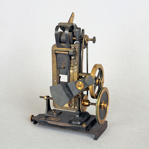
Projecteur de film 35 mm
N° Inventaire : AP-94-93(1/2)
Collection : La Cinémathèque française
Catégorie d'appareil : Projection lumineuse cinématographique
Nom du modèle : N & G Kinematograph Projector
Lieu de fabrication : Londres, Grande-Bretagne
Année de fabrication : 1898
Brevet : Arthur Samuel Newman, B.P. n° 22 707, 13 octobre 1896 : "Improvements in Kinematograph Apparatus" Arthur Samuel Newman, Newma... +
Copyright photo : Dabrowski Stéphane
Fiche détaillée
Type de l'appareil
entraînement du film 35 mm Edison ou Lumière par deux griffes ; came excentrique ; obturateur une pale ; poulie d'entraînement ; volant ; trois galets ; régulateur de vitesse ; boîte de transport en bois
Auteurs
Newman Arthur Samuel
Londres, 92 Shaftesbury Avenue
Guardia
Londres, 92 Shaftesbury Avenue
Fabricants
Newman & Guardia Ltd
Harlow, Essex
Utilisateurs
Newman Arthur Samuel
Londres, 92 Shaftesbury Avenue
Guardia
Londres, 92 Shaftesbury Avenue
Distributeurs
Informations non disponibles
Sujet du modèle
Informations non disponibles
Objectif
absent
Taille de l'objet
Ouvert :
Informations non disponibles
Fermé :
Longueur : 13 cm
Largeur : 22.5 cm
Hauteur : 32.5 cm
Diamètre :
Informations non disponibles
Taille de la boîte de transport
Informations non disponibles
Remarques
Plaque de cuivre : "Newman & Guardia LTD, London, Patent".
"The machine has a distinctive appearance quite unlike any other projector of the period " (J. Barnes). Il existe un modèle de 1899, légèrement différent, au Science Museum de Londres.
"The film-spool is dropped into a self-adjusting slide at the top, and the end of the film is led between rollers, which drive it by friction on the margin only. These rollers themselves are frictionnaly driven, and therefore plucking of the film is impossible. A slight turn of the handle drives the film under the curved guard, the film-trap is thrown up on its hinge, under which the film is inserted from the side, and then hangs free over a perfectly clear metal plate. Through two slots in this plate two pins protrude, the film is adjusted so that these pins engage with a pair of perforations, the film-trap is let down and the clamping-bar locked over it, and the machine is then ready to work. The fly-wheel seen on the right acts as a speed-regulator, while it will be noticed that the balanced shutter in front is of extremely small angular dimensions. It occupies barely one-twentieth of its circular path, which is equivalent to saying that over nineteen-twentieths of the light passes to the screen, a practically unsurpassable degree of efficiency. Also the period of rest is nineteen times as long as the period of movement [...]. The method by which the pins are actuated ; they are shown passing through the slotted plate and film perforations, having just arrived at the end of their stroke. They have been drawn into this position by two springs, one pulling downward, the other drawing the teeth forward. Arrived at the bottom of the slot, and having thereby placed a picture in exact position, the cross-bar is tightened by a cam, and thus grips the film securely between the film-trap and the main-plate. This done, a little peg on the rotating disc, comes round from right to left at the bottom, catches under a shoulder in the lever bearing the pins, and forces them backwards out of the perforations. Continuing its motion, this peg carries the pins backwards and upwards against the action of the springs. Arrived at the top of its path, the motion of the pins becomes forward, and the lever then stands in the position shaded on the diagram, the pins being omitted for the sake of clearness. The peg continues on its way, but the lever cannot follow it because it butts against a cam-surface. The peg therefore passes from under the shoulder on the lever, and continues its journey back to the position in which we first found it. At this moment the springs become free to act, and the levers are drawn down as quick as thought. The clamping-bar in front has been released just previously, and the upper feed-rollers have been paying out another picture-lenght ; consequently the pins have no weight thrown upon them, and act rather as guides. An adjustable dash-pot buffers the end of the stroke, and the whole is now in the position from which we started. The pins are primarily arranged to engage with holes situated at the centre of each side of the picture, their ends being tapered so that they will enter a hole which is slightly out of gauge and briing it into exact position by passing right into it. On turning the snail-shaped releasing cam, the lever may be freed somewhat sooner, and the points being tapered chisel-fashion, they will therfore enter Edison or other perforations equally well. The whole apparatus is fitted on a base-board which slides on guides in front of an N. and G. lantern, other projection fittings sliding to the same gauge ; in fact, a sideway sliding-base enables Kinematograph, ordinary projection front or lantern-microscope to be alternately centred to the condenser at a moment's notice" (Henry Hopwood, Living Pictures, Londres, Optician & Photographic Trades Review, 1899, p. 179-183). A noter que sur la photo reproduite par Hopwood, l'appareil est équipé de pellicule Lumière.
Bibliographie
Henry Hopwood, Living Pictures, Londres, Optician & Photographic Trades Review, 1899, p. 179-184.
J. Barnes, Pioneers of the British Film, Londres, 1983, pp. 108-110.